功率因数修正电路
功率因数修正电路(power factor correction)简称PFC,是可以改善交流电源端功率因数的电路。是开关模式电源中常见的电路之一。 可分为被动功率因数修正(无源功率因数修正、passive PFC)、主动功率因数修正(有源功率因数修正、active PFC)及动态功率因数修正(Dynamic PFC)。

被动功率因数修正
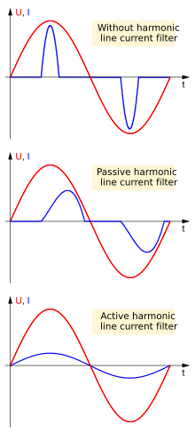
编辑最简单降低谐波电流的方式是使用只含有被动(无源)元件的滤波器,此作法称为被动功率因数修正或无源功率因数修正(passive PFC)。
对于谐波电流,可设计一滤波器,只让基频(50或60Hz)频率的电流通过,滤波器可降低谐波电流,因此会使非线性元件的输入电流会和线性元件比较接近。若要使功率因数尽可能接近1,需要使用电容器或电感器或两者并用。一般这类的滤波器需使用大电流的电感器,其体积也比较大。相较于主动功率因数修正(active PFC)的电感器,被动功率因数修正需要的电感器体积较大,但价格较低[1][2]。
除了使用电容器、电感器的组合外,也可以使用电容器组来修正负载的非线性电流,其中一个例子是使用填谷式电路。被动式功率因数修正的修正效果,电感器电容器组合电路修正后的功率因数在0.7至0.8之间,填谷式电路的则在0.9左右或更高一些。但效果仍不如主动功率因数修正,产生的热量较主动式功率因数修正的要大些[3][4][5][6][7]。
而被动功率因数修正的电效率一般较主动功率因数修正要好。电脑电源供应器的被动功率因数修正其效率一般到达96%左右,而一般主动功率因数修正效率约为94%。此外,一般被动式功率因数修正的电路会比主动式功率因数修正的要简单,工作更为可靠稳定。[8]
主动功率因数修正
编辑主动功率因数修正或有源功率因数修正(active PFC)是指可调整负载的输入电流,改善功率因数的电力电子系统,其主要目的是使输入电流接近纯电阻式负载的电流,使其视在功率等于有功功率[9]。理想状态下其电压和电流相位相同,而其产生或消耗的无功功率为0,使电源端可以最有效率的传递能量给负载[10]。
以下是一些主动功率因数修正的分类:
- Boost转换器(升压)
- Buck转换器(降压)
- Buck-boost转换器(升降压)
主动功率因数修正可以是单级的电能转换,也可以是多级的电能转换。
以电源供应器为例,Boost转换器会放在整流二极管和主电容器之间。Boost转换器会设法在输入电流和电压同相位及相同频率的条件下,维持其输出是一固定的直流电压。电源供应器中另一个开关电源将固定的直流电压转换为需要的输出电压。此作法会需要增加半导体开关及电子控制线路,但其被动元件的体积会比较小,在实务上常常使用。
有些设计会用二组的Boost转换器,轮流启动,二组转换器产生的涟波电流有部分会互相抵消,输出涟波电流会比较小,即为交错式(interleaving)功因修正[11]。
若是三相交流输入的电源供应器,可以用Vienna整流器组态来提升功率因素。
有主动功率因数修正的开关电源,功率因数最高可以到0.99,而没有功率因数修正的开关电源,其功率因数只有0.55–0.65[12]。
由于其输入电压的范围相当广,许多有主动功率因数修正的电源供应器可以配合输入电压自动调整,电压范围由100V(日本)到230V(欧洲),功率较大的笔记式电脑的电源供应器多半都有此功能。
动态功率因数修正
编辑动态功率因数修正(Dynamic PFC)是指利用电力电子设备(如闸流体)高速开关电容及电感来提高系统的功率因数。传统的控制方法(断电器)需要数秒的反应时间,无法应付快速改变的负载,而且只能开关特定数量的电容器组。使用闸流体的电容器组只需要一个周期(50Hz电源的周期是20ms,60Hz电源的周期是16.67ms)的反应时间,而且能改变输出功率。
参考资料
编辑- ^ "Power Supply Design Principles ... Part 3" (页面存档备份,存于互联网档案馆) by Ben Schramm
- ^ "Quasi-active power factor correction with a variable inductive filter: theory, design and practice" (页面存档备份,存于互联网档案馆) and "Quasi-active Power Factor Correction: The Role of Variable Inductance" (页面存档备份,存于互联网档案馆) by Wolfle, W.H.; Hurley, W.G.
- ^ "ATX Power Supply Units Roundup" (页面存档备份,存于互联网档案馆) The power factor is the measure of reactive power. It is the ratio of active power to the total of active and reactive power. It is about 0.65 with an ordinary PSU, but PSUs with active PFC have a power factor of 0.97-0.99. ... hardware reviewers sometimes make no difference between the power factor and the efficiency factor. Although both these terms describe the effectiveness of a power supply, it is a gross mistake to confuse them. ... There is a very small effect from passive PFC – the power factor grows only from 0.65 to 0.7-0.75."
- ^ "The Active PFC Market is Expected to Grow at an Annually Rate of 12.3% Till 2011" (页面存档备份,存于互联网档案馆) "Higher-powered products are also likely to use active PFC, since it would be the most cost effective way to bring products into compliance with the EN standard."
- ^ TECHarp: "Power Factor Correction" (页面存档备份,存于互联网档案馆) "Passive PFC ... the power factor is low at 60-80%. ... Active PFC ... a power factor of up to 95%"
- ^ "Why we need PFC in PSU" (页面存档备份,存于互联网档案馆) "Normally, the power factor value of electronic device without power factor correction is approximately 0.5. ... Passive PFC ... 70~80% ... Active PFC ... 90~99.9%"
- ^ "PFC options for power supplies" (页面存档备份,存于互联网档案馆) by Tom Brooks 2004 "The disadvantages of passive PFC techniques are that they typically yield a power factor of only 0.60 to 0.70 ... Dual-stage active PFC technology [yields] a power factor typically greater than 0.98"
- ^ "Comparison between passive and active PFC solutions for a 250-W ATX application.". [2012-06-06]. (原始内容存档于2012-06-25).
- ^ Fairchild Semiconductor (2004). Application Note 42047 Power Factor Correction (PFC) Basics. Retrieved from http://www.fairchildsemi.com/an/AN/AN-42047.pdf (页面存档备份,存于互联网档案馆)
- ^ Bollen, M. H. J. (1999). Understanding Power Quality Problems: Voltage Sags and Interruptions. Piscataway, NJ: Wiley-IEEE Press
- ^ Advantages of interleaved boost converters for PFC. [2020-08-20]. (原始内容存档于2020-08-20).
- ^ Sugawara, I., Suzuki, Y., Takeuchi, A., & Teshima, T. (1997). Experimental studies on active and passive PFC circuits. Telecommunications Energy Conference, 1997. INTELEC 97., 19th International 19-23 Oct 1997. 571-578. doi 10.1109/INTLEC.1997.646051.
相关条目
编辑外部链接
编辑- Interaktives Leistungselektronik-Seminar(页面存档备份,存于互联网档案馆)
- Das neue InterNetzteil- und Konverter-Handbuch. Kapitel 12: Passive und aktive Netzfilter/Leistungsfaktorkorrektur(页面存档备份,存于互联网档案馆)
- Leistungsfaktorkorrektur mit Cuk-Konverter(页面存档备份,存于互联网档案馆)
- Power Topology Considerations for Electric Vehicle Charging Stations (页面存档备份,存于互联网档案馆)