Footprint
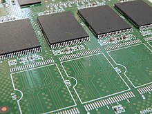
footprint是印刷电路板上针对表面安装技术(SMT)器件接触焊点的配置,或是通孔插装技术的通孔配置,目的是让电气器件及集成电路可以固定在印刷电路板上,且可以和电路的其他部分相连接[1]。电路板上的footprint需要和器件的引脚一致。


器件制造商一般会对一个产品生产许多和其他竞品针脚兼容的型号,让系统整合者方便更换零件,不需要修改印刷电路板上的footprints。这对系统整合者降低成本很有帮助,尤其是针脚很密集的球栅阵列封装(BGA)器件,其中的焊点可能会连接到印刷电路板上的其他层。
许多器件制造商(像是德州仪器[2]及CUI[3])也会提供其器件的footprint资料。footprint的来源也包括第三方厂商,例如SnapEDA[4][5]。
相关条目
编辑参考资料
编辑- ^ IPC-7351 - Generic Requirements for Surface Mount Design and Land Pattern Standard. IPC. 2005: 4.
- ^ Texas Instruments. [2020-01-22]. (原始内容存档于2020-01-22).
- ^ CUI. [2020-01-22]. (原始内容存档于2019-07-31).
- ^ SnapEDA. [2020-09-25]. (原始内容存档于2020-09-23).
- ^ Top 10 websites to find footprints for your next PCB project. Electronics-Lab. 2019-07-26 [2019-07-31]. (原始内容存档于2019-07-31) (美国英语).